Attaching and adjusting control surfaces to tail cone
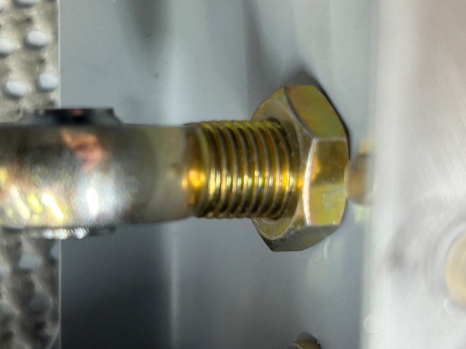
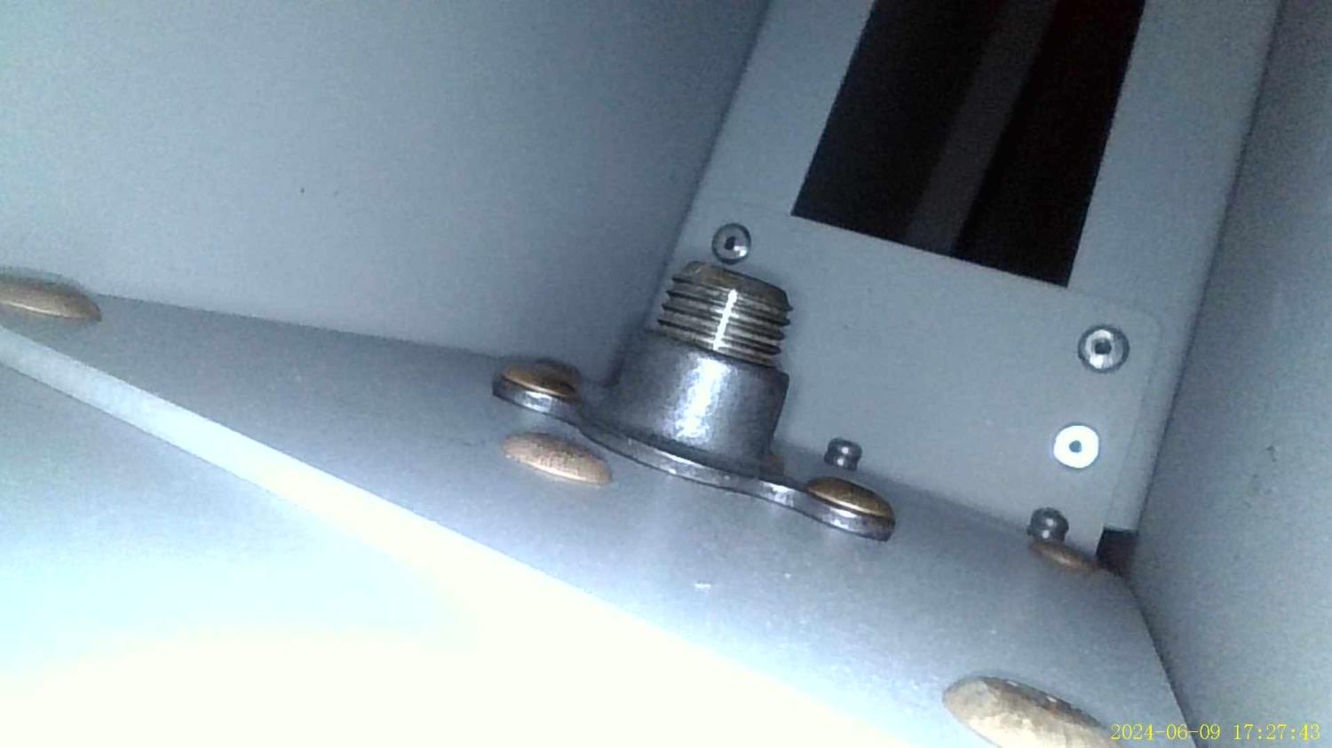
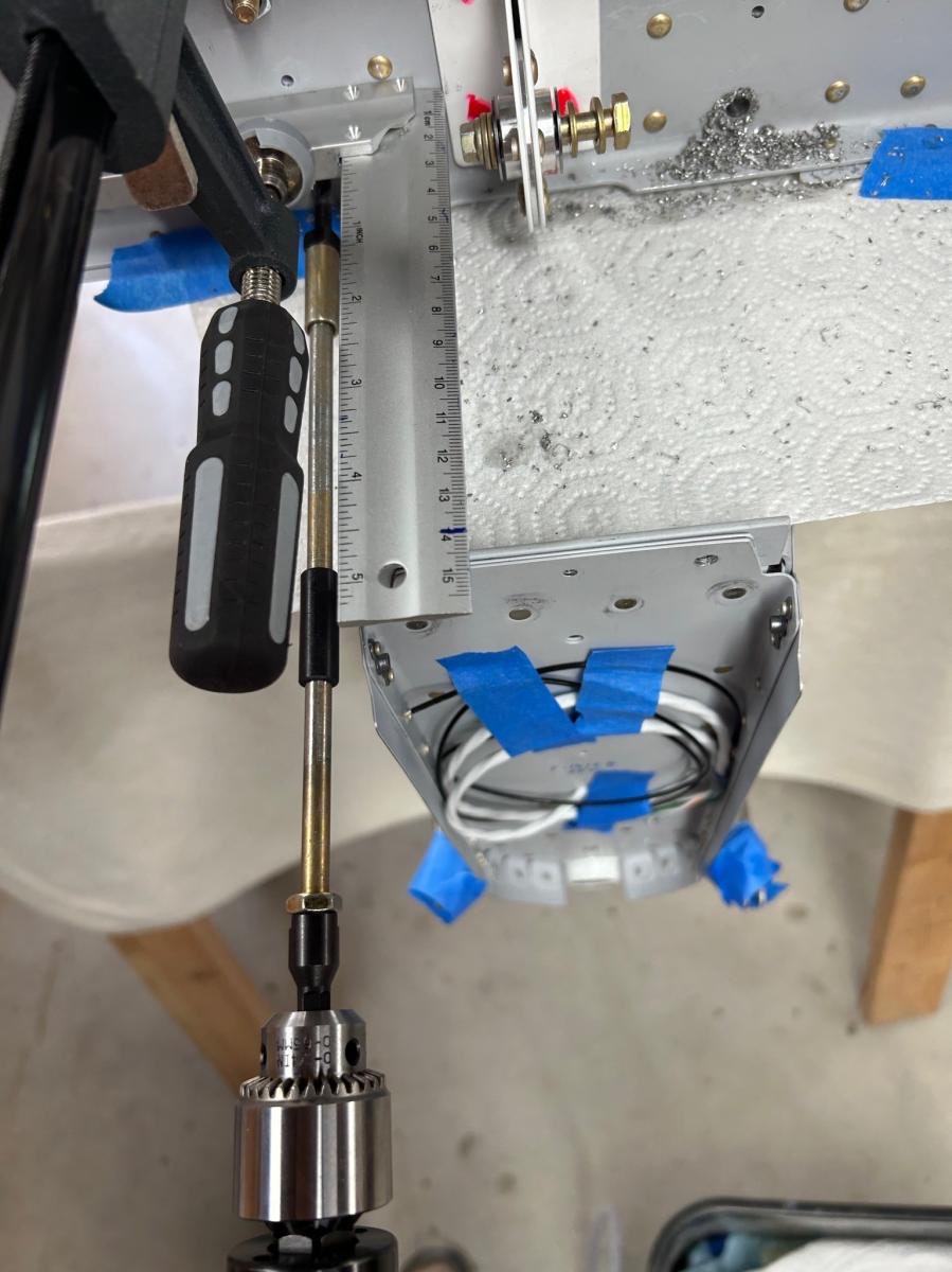
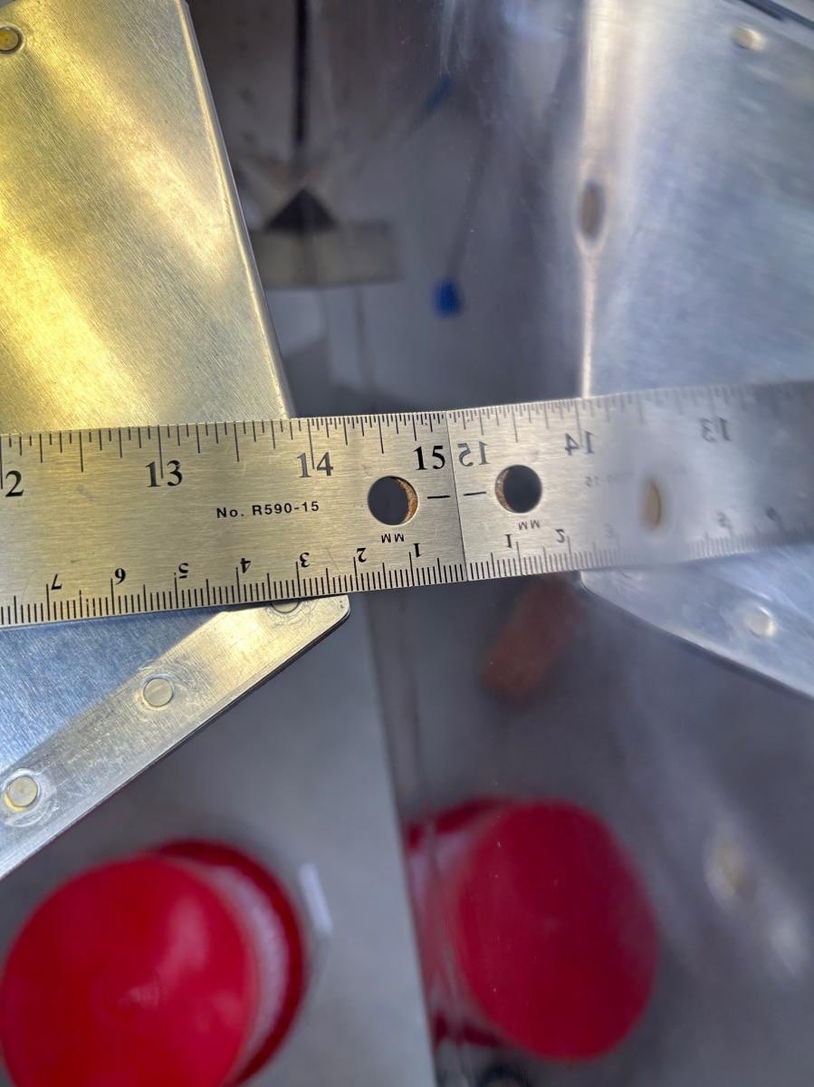
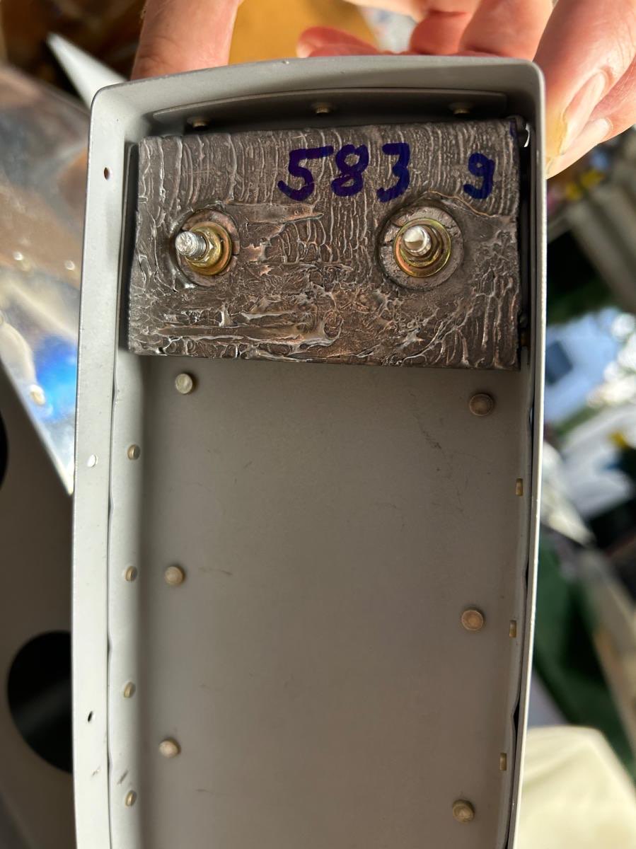
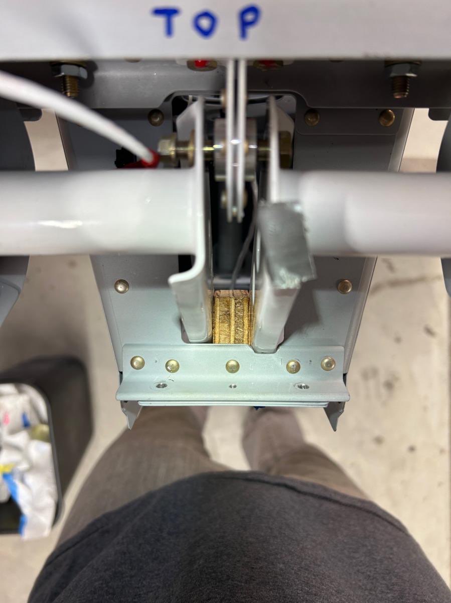
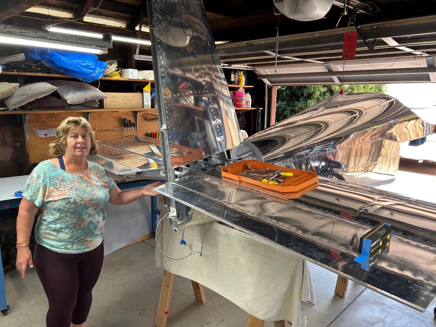
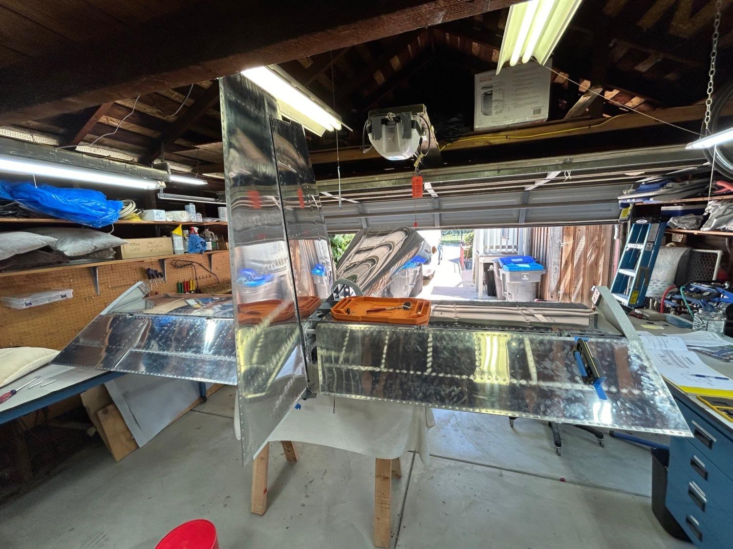
June 5-11, 2024 HS attach - needed to drill some holes to 1/4” final size, and the lower holes couldn’t be reached with my drilling gear. Paul Mantegna pointed out that I could make a drill extension using threaded-shank bits, using our threaded deburring extension. I had everything needed, but for large threaded drill bits, which I borrowed from Andrew Clark (and then ordered my own). The job went easily with the right tools, as usual! VS attach - this was easy since the holes were all drilled already, just needed to bolt it in place (I used temporary wing nuts and steel bolts, to not wear out the real lock nuts. With HS and VS properly mounted, this led to the most satisfying part of the build so far, which was hanging the rudder and elevators, and seeing the whole tail of the airplane in nearly final shape! It also allows measuring and adjusting control surface deflection, and checking that the rudder stops prevent the rudder and elevator from colliding with a safe margin (spec is 0.75” minimum gap, and ours was about 0.9” on both sides. I was very happy about this, since the rudder stops were crudely cut to shape with a hack saw! Until now, the rudder was held by only the upper and lower hinge pins. The middle pin gets installed last, and required lots of iteration adjusting the middle rod-end to get the hole to line up with the steel hinge bracket. When I achieved this, I used the borescope to check thread engagement with the nut plane inside the rudder, and there were no threads protruding, which is a problem. So, I installed a longer control rod end which I had already ordered from Van’s since I knew this was likely (in my opinion, they should just ship the longer one with the kit, since almost everyone has the problem!). Problem solved, and now the rudder rode ends can be torqued into final position. There is a photo below from the borescope with the longer rod-end showing proper thread engagement. I measured elevator travel limits to be 23 degrees down (spec is 20-25) and just over 25 up (spec is 25-30). I was uncomfortable being so close to the minimum for up-travel, so I filed a notch into the aft deck angle (see photos) where the right elevator control horn was hitting. I filed until both control horns would simultaneously hit the deck angle, and this resulted in 28 degrees of elevator up travel - perfect! The last issue was finalizing the elevator counterbalance weights, since this was a convenient time to do it. An email exchange with Van’s tech support said to balance each elevator individually, slightly nose heavy to account for later painting which will add tail weight. No details on how much nose heavy though! The right elevator was already nose heavy (by about 70 grams at the counterweight location), so I left it as is. The left elevator was tail heavy, due to the trim servo actuator, and I found I needed to add about 160 grams to the left outer counterweight to get it to match the slight nose-heaviness of the right elevator. I added the mass by melting lead and pouring it onto the surface of the counterweight, increasing its weight from about 570 grams to 730 grams. Then I bedded all the counterweights in marine 5200 sealant, and bolted them on and torqued the AN3 fasteners to final torque. Once the elevator tip fairings are installed, these weights cannot be worked on any more, except for removing lead from the inner, still-accessible weight on each elevator horn. In case more weight is needed after painting, I’m going to install an AN3 nutplate to each counterweight rib, so some heavy fender washers can be added after painting if necessary to balance the elevators. Next steps - add the elevator nut plates, and then start working on fiberglass fairings!
Time spent: 19hr